
What determines antenna selection for an RS103 system?
Selection is driven by the required frequency range and field strength, test distance, chamber geometry, amplifier output, cable loss, polarization and the antenna power-handling limit.
A high-field antenna family spanning low-frequency power transmission, broadband immunity testing and millimeter-wave extensions.
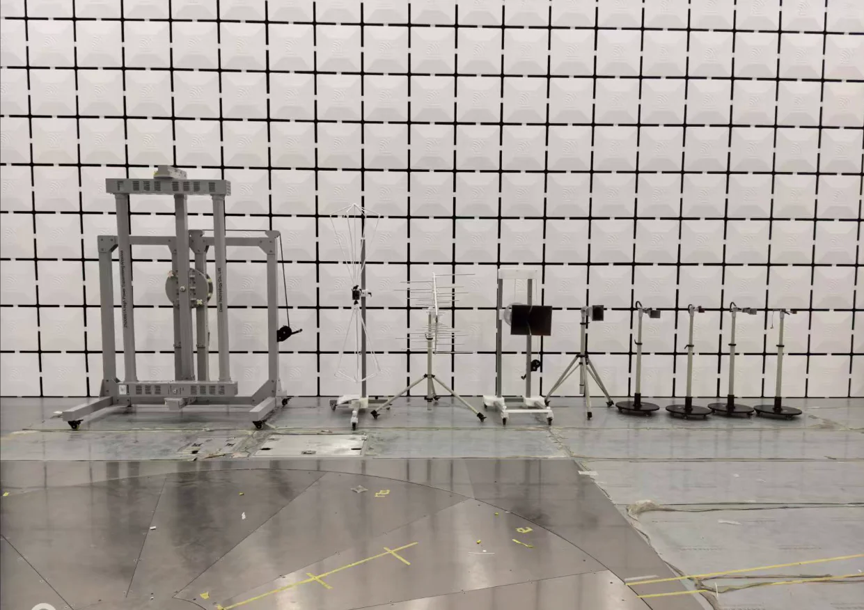
Ten antenna models are available across the complete 10 kHz–70 GHz family. The actual supplied system is selected around target field strength, test distance, amplifier power and the required upper frequency.
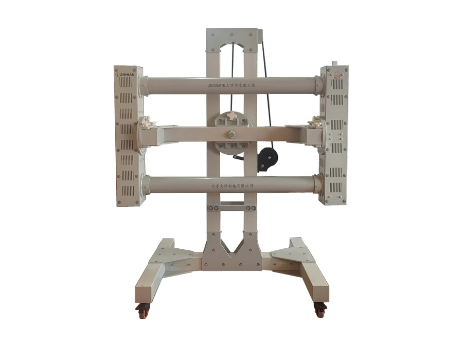
Low-frequency high-power transmit antenna for high-field RS103 testing.
View antenna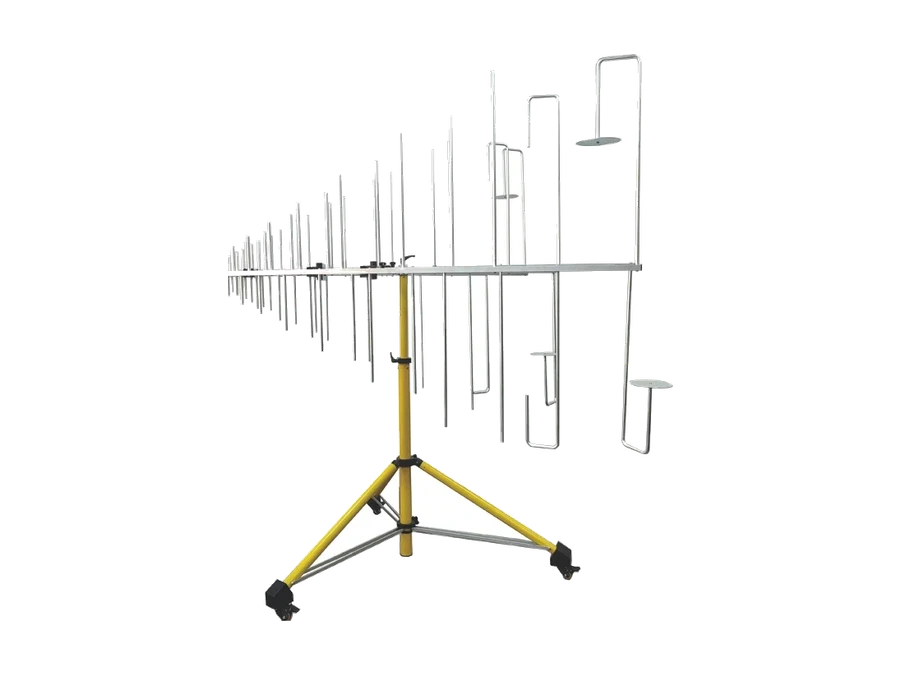
Single-antenna broadband route for high-field coverage through 1.5 GHz.
View antenna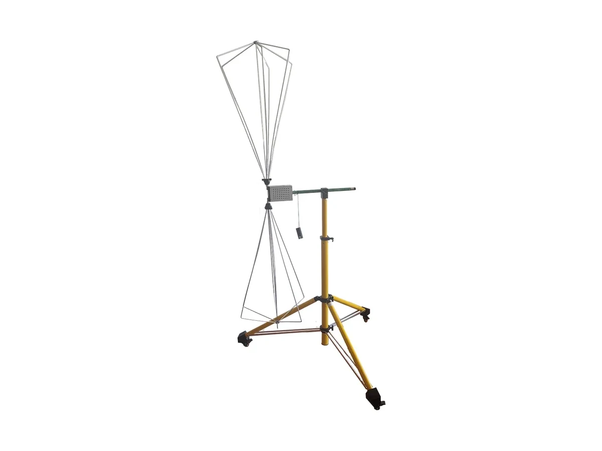
High-power biconical antenna for the lower part of the segmented broadband route.
View antenna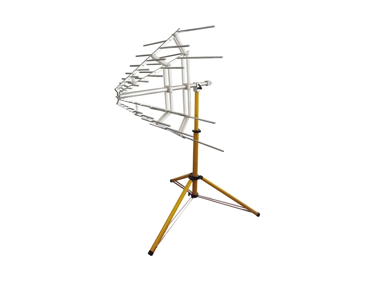
Stacked log-periodic antenna that completes the segmented broadband route.
View antenna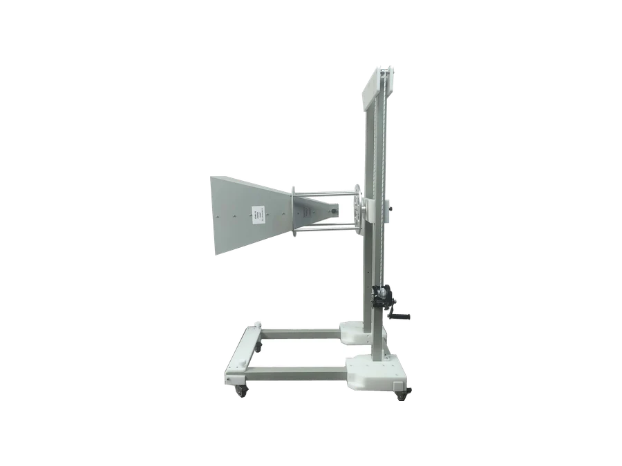
High-power double-ridged horn for the lower microwave range.
View antenna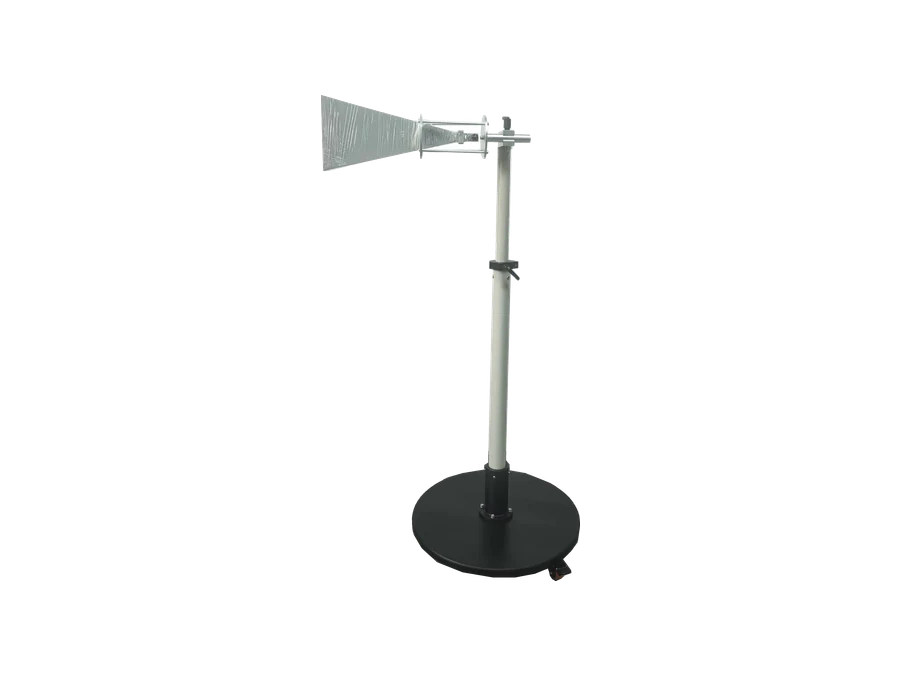
High-gain double-ridged horn for the upper microwave range.
View antenna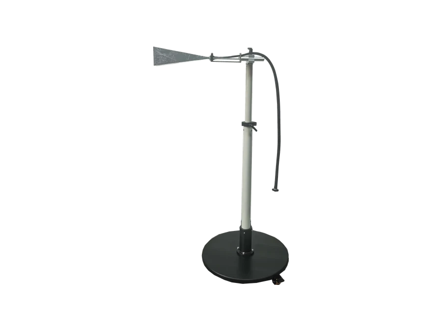
Pyramidal horn transmit antenna for the first millimeter-wave extension.
View antenna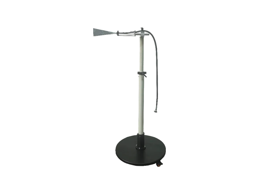
Ka-band pyramidal horn transmit antenna.
View antenna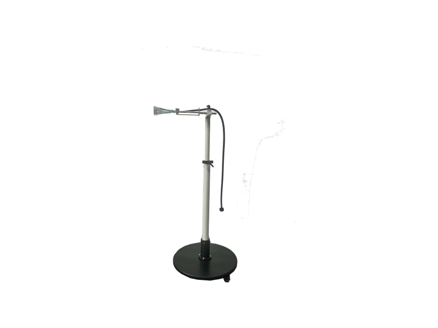
Measurement horn used as the RS103 transmit extension through 50 GHz.
View antenna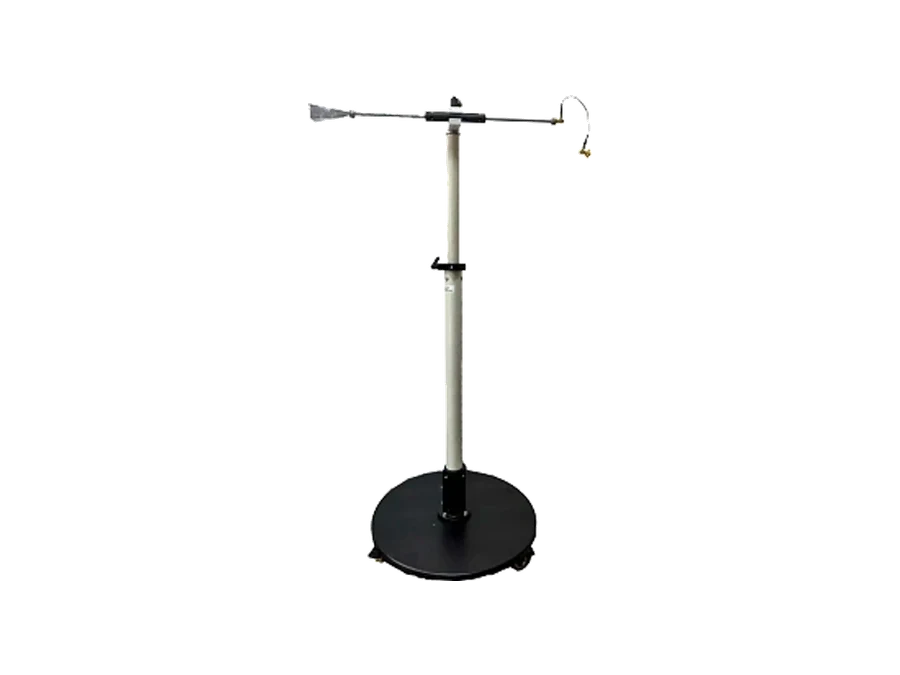
Measurement horn that extends the RS103 transmit chain to 70 GHz.
View antennaThese answers define the normal engineering starting point. Final antenna and amplifier selection is based on the required field at the actual test distance.
Selection is driven by the required frequency range and field strength, test distance, chamber geometry, amplifier output, cable loss, polarization and the antenna power-handling limit.
No. The ten models form the available full-band family. A project uses only the antenna route needed for its frequency range, target field and facility constraints.
The ZN30505M provides a single-antenna broadband route through 1.5 GHz. The ZN30505A-S and ZN30505K form a segmented alternative that can be selected around power, gain and chamber requirements.
A complete chain normally includes signal generation, power amplification, directional coupling, forward and reflected power monitoring, field probes, RF cables, adapters, mounts and control or interlock functions.
Share the frequency range, target field strength, test distance and chamber conditions so the antenna, amplifier, monitoring and control chain can be matched.